Views: 132 Author: Site Editor Publish Time: 2026-08-01 Origin: Site
Selecting the right fluid control components requires balancing power demands against system efficiency. Undersizing a valve causes excess heat generation. It also creates restrictive pressure drops. Oversizing leads to poor metering precision. It drives up unnecessary component costs. For mobile and industrial hydraulic systems, the DCV series provides sectional versatility. Engineers routinely evaluate the 60 L/min, standard 100 L/min, and heavy-duty 140 L/min variants. Selecting the wrong flow rating limits machine capability.
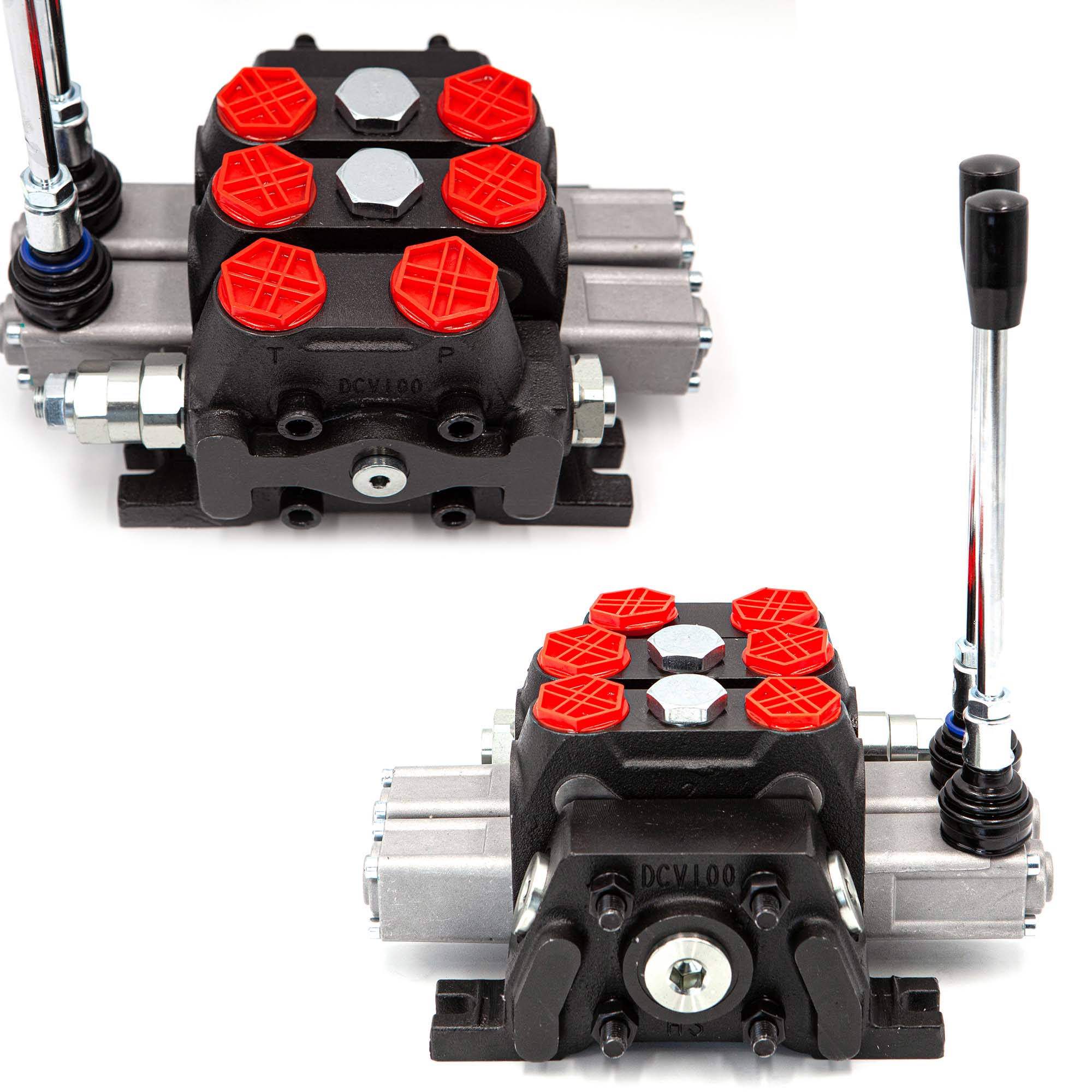
This guide compares the operational limits of the DCV100 60L/min control valve against the DCV100 140L/min control valve. We provide a structured technical framework for proper valve sizing. You will learn how to optimize flow velocities and avoid common engineering pitfalls. Proper sizing directly improves cycle times and system reliability.
Flow dictates heat and efficiency: Valve sizing must account for peak return flow, not just pump supply, to prevent excessive pressure drop (ΔP).
60 L/min applications: Ideal for auxiliary circuits, compact agricultural equipment, and attachments requiring precise, low-flow metering.
140 L/min applications: Necessary for main drive circuits, heavy earthmoving equipment (e.g., scooptrams), and multi-actuator simultaneous operations.
Sectional vs. Monoblock: Sectional DCV valves allow modular integration of relief valves, 4-way 3-position spools, and spring-return manual controls tailored to exact machine specs.
An improperly sized directional control valve directly impacts machine performance. It reduces cycle times and degrades fuel efficiency. These issues stem from hydraulic horsepower loss. When a hydraulic system forces fluid through a restrictive passage, energy converts into heat. You lose productive mechanical work. Addressing this business problem early prevents costly machine downtime.
The pressure drop (ΔP) rule dictates system efficiency. Fluid encounters resistance as it moves through valve galleries. Forcing 100 L/min through a valve rated for 60 L/min causes exponential issues. The pressure drop does not scale linearly. It spikes dramatically. This massive pressure drop translates directly into extreme heat generation. Heat degrades hydraulic oil viscosity. It accelerates seal wear and ruins internal O-rings.
Many engineers fall into the oversizing trap. They assume larger valves offer a safer safety margin. Defaulting to the largest valve is a mistake. Oversized valves ruin fine spool metering. Operators lose precision control during delicate machine movements. A massive valve also introduces heavier physical weight. It demands a larger mounting footprint on compact machines. Furthermore, you face higher initial procurement costs for unneeded capacity.
The 60 L/min configuration delivers highly precise fluid control. It handles lower flow volumes efficiently. Engineers design these models for systems producing lower peak flows. They operate best within standard 40-50 L/min pump outputs. Pushing flow near the absolute 60 L/min maximum remains safe. However, maintaining a slight margin ensures optimal thermal performance.
We typically see this variant deployed in specific equipment categories. Consider these ideal use cases:
Compact mobile machinery, including mini-excavators and small skid steers.
Compact agricultural tractors needing responsive implement control.
Secondary auxiliary functions on much larger machinery.
Hydraulic clamp mechanisms, stabilizers, and outriggers.
Performance metrics favor the 60 L/min size for sensitivity. It maintains a significantly lower pressure drop at standard 40 L/min flows. The internal design features tighter spool-to-bore clearances. These tight tolerances allow highly sensitive manual control. Operators can feather the control levers easily. They achieve smooth, predictable cylinder movements during delicate operations.
Heavy-duty machines require massive fluid transfer. The 140 L/min high-capacity variant meets these extreme demands. It provides enormous internal flow galleries. It sustains high-velocity fluid movement safely. This variant handles immense fluid volumes during rapid actuator cycles. It excels in extreme industrial environments.
This massive flow capacity suits demanding applications. Ideal use cases include:
Primary actuation circuits in heavy construction equipment.
Large mining vehicles, such as scooptrams and massive wheel loaders.
High-demand hydraulic motors powering rotary drives.
Large-bore cylinder operations lifting extreme payloads.
The design advantages focus entirely on fluid velocity management. Larger internal gallery sizes handle high-velocity return fluid effortlessly. They prevent flow bottlenecks inside the valve body. Restrictive bottlenecks often trigger premature relief valve opening. The 140 L/min variant eliminates this risk. It keeps the system running smoothly under heavy loads. It also mitigates thermal expansion issues during continuous heavy operation.
Selecting the correct Directional Control Valve requires a structured approach. Guessing flow rates leads to systemic failures. Follow this sequential framework to guarantee precise sizing.
You must not base sizing solely on pump supply limits. Pump output only dictates the incoming fluid volume. The implementation reality requires examining hydraulic cylinders. You must account for the differential area of these cylinders. A retracting cylinder pushes fluid out of its cap end. The cap end holds a larger fluid volume than the rod end.
This returning fluid volume easily exceeds the pump supply rate. Retraction can push significantly more fluid back through the valve. If you size the valve based on pump flow alone, return flow chokes. This creates massive pressure spikes. Always calculate the maximum return flow velocity before finalizing your selection.
Flow capacity represents only half the engineering equation. Pressure ratings complete the picture. You must verify the valve housing material thoroughly. Standard cast iron suits many applications. However, nodular iron provides superior tensile strength. It handles extreme pressure environments better.
The housing must sustain the continuous operating pressure safely. It must also absorb peak shock loads safely. Heavy machinery experiences sudden mechanical shocks during digging or lifting. These mechanical shocks translate into hydraulic pressure spikes. Ensure your selected valve rating exceeds these intermittent shock loads.
Spool logic dictates how fluid routes through the system. You must select spool types based on your pump architecture. Open center spools work alongside fixed displacement pumps. They return fluid to the tank during neutral positions. Closed center spools pair with variable displacement pumps. They block flow to build standby pressure.
Evaluate your manual control features carefully. Standard 4-way 3-position configurations dominate the market. You must choose between spring return and detent mechanisms. Spring return automatically centers the spool upon release. Detent mechanisms hold the spool in a shifted position. Select the mechanism matching your operator safety requirements.
Machine designs evolve rapidly. You must evaluate the need for modularity. Monoblock valves offer a compact, single-cast solution. However, they lack expansion capabilities. Sectional valves provide tremendous flexibility. They allow you to stack individual functional slices together.
Determine if future machine iterations will require additional actuators. You might need an extra auxiliary circuit later. Sectional expansion lets you add functional slices easily. You avoid replacing the entire valve bank. This modular approach saves engineering time during future machine upgrades.
Valve Specification Reference Chart
Specification Parameter | 60 L/min Variant | 140 L/min Variant |
|---|---|---|
Optimal Pump Output | 40 - 50 L/min | 100 - 130 L/min |
Maximum Safe Flow | 60 L/min | 140 L/min |
Primary Application | Auxiliary / Compact Machinery | Main Drive / Heavy Earthmoving |
Spool Metering Precision | High (Tight Clearances) | Standard (High Volume Focus) |
Internal Gallery Size | Standard | Enlarged for Return Velocity |
Selecting the valve represents the first phase. Implementation carries specific engineering risks. Port sizing mismatching happens frequently. You risk mismatching valve port sizes with existing hose assemblies. Common standards include BSP, NPT, and SAE O-ring boss. A mismatch forces engineers to use restrictive adapters. These adapters cause severe flow restrictions. They introduce localized pressure drops right at the valve inlet.
Contamination sensitivity requires strict attention. Higher-flow valves process massive fluid volumes daily. Valves operating near maximum capacity are highly sensitive to fluid contamination. Debris damages internal spool lands quickly. You must outline strict ISO filtration requirements. Maintaining fluid cleanliness to ISO 4406 standards prevents premature spool binding. It also protects internal check valves from seating failures.
Supply chain constraints impact production timelines. Standard 60-100 L/min models remain highly commoditized. Distributors stock them globally. Highly customized 140 L/min sectional configurations tell a different story. These specialized assemblies often require longer B2B procurement lead times. You must factor these lead times into your manufacturing schedule. Early technical consultation prevents costly assembly line delays.
Sizing a directional control valve is a strict balancing act. You must balance fluid velocity limits against control precision. Undersizing generates system-destroying heat. Oversizing wastes capital and ruins fine operator control. The correct choice stabilizes machine performance instantly.
Use clear shortlisting logic for your projects. Choose the 60 L/min variant for auxiliary circuits and compact precision. Select the 140 L/min variant for high-volume, heavy-duty primary circuits. Always prioritize the maximum cylinder return flow during calculations.
Take proactive next steps today. Encourage your engineers and procurement managers to review official pressure drop curves. Analyze the ΔP vs. Flow charts meticulously. Consult a technical specialist to finalize spool configurations and porting sizes. Precision engineering at this stage guarantees long-term hydraulic reliability.
A: Forcing excess flow causes a severe pressure drop. This restriction generates excessive heat rapidly. The extreme temperatures cause fluid degradation and viscosity breakdown. Thermal expansion inside the valve body can lead to severe spool binding. This ultimately damages internal seals and halts machine operation entirely.
A: Generally, no. Sectional valves utilize specific manifold tie-rod assemblies. Mixing different bore and slice sizes presents physical mounting limitations. They require matching internal gallery alignments. Hydraulic limitations also exist, as mixing extreme flow disparities complicates return line pressures. You should use separate valve banks for vastly different flow requirements.
A: This terminology describes the spool functionality. "4-way" indicates four working ports (Pressure, Tank, A, and B). "3-position" means the spool shifts into three modes: extend, retract, and a neutral center. "Spring return" indicates a mechanical spring mechanism. It forces the spool back to neutral automatically when the operator releases the handle.