Views: 0 Author: Site Editor Publish Time: 2026-10-12 Origin: Site
Mobile equipment engineers constantly face a strict physical battle. They require immense lifting power and a long operational stroke. However, they must fit this machinery into a highly restricted mounting envelope. Specifying a lift mechanism requires balancing the necessary dump angle against strict fluid mechanics. As tubular stages nest together, they alter the overall force output during extension. You cannot simply guess the necessary dimensions or pressure limits. Guesswork leads to catastrophic equipment failure or stalled loads.
This article provides procurement and engineering teams a solid technical framework. We will help you evaluate stage counts accurately. You will learn how to calculate lift force drop-offs across different cylinder extensions. Furthermore, we will guide you in selecting the optimal configuration for any specific truck chassis. Understanding these mechanical relationships ensures safe, efficient, and reliable operations on the job site.
Stroke Optimization: Multi-stage designs offer a stroke-to-retracted-length ratio of up to 6:1, compared to 2:1 for standard rod cylinders.
Force Degradation: Lifting force decreases with each successive stage extension due to the diminishing effective surface area of the internal plungers.
System Sequencing: The largest diameter stage always extends first to provide maximum initial breakaway force for heavy, static loads.
Application Match: Most dump bodies rely on gravity-return designs, making the proper sizing of a single acting telescopic cylinder critical for safe, consistent operation.
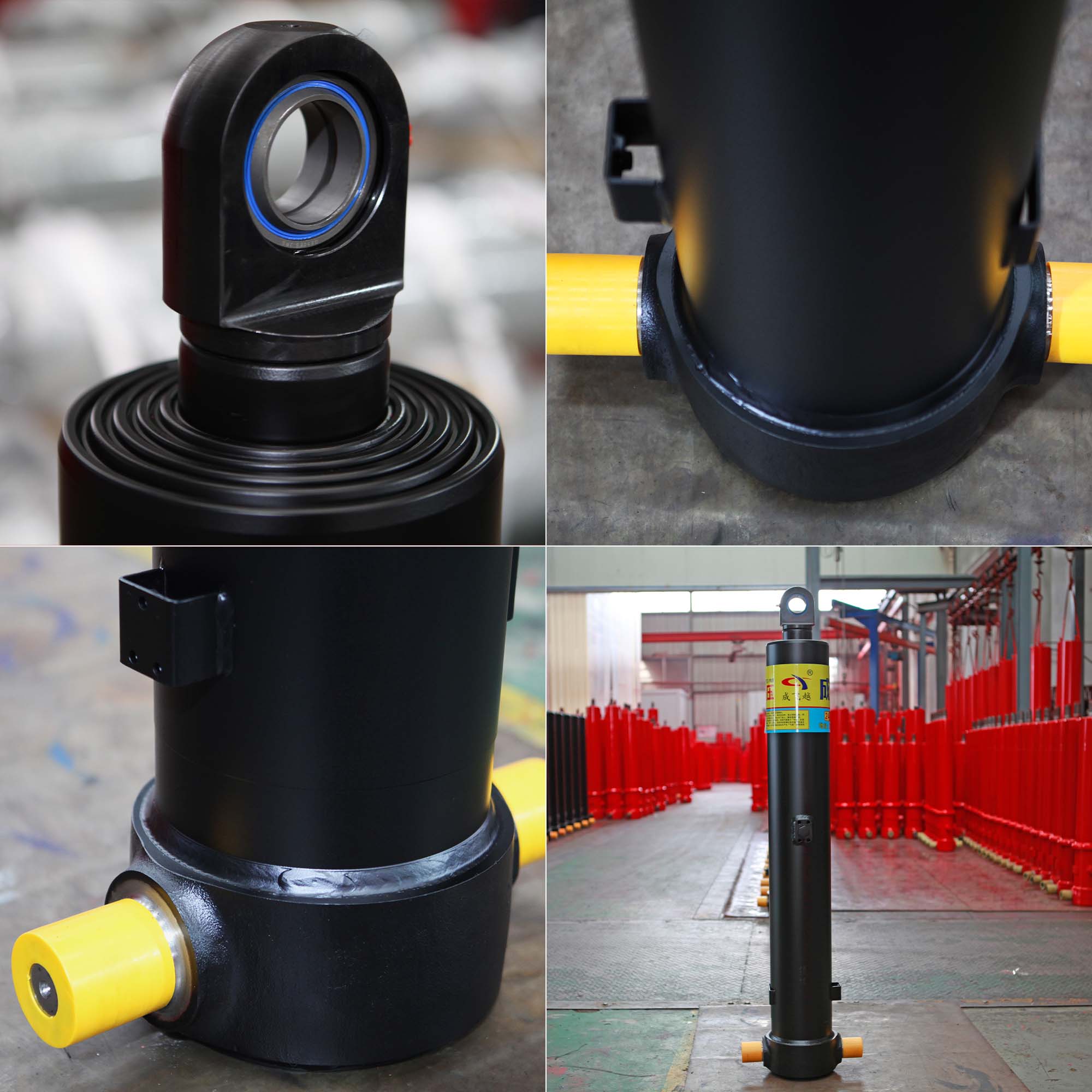
A standard rod cylinder only extends roughly its own length. It achieves a basic 2:1 ratio. This falls drastically short for most modern mobile equipment. Heavy-duty trucks require significant tilt angles to empty materials efficiently. You achieve this necessary reach utilizing concentric sleeves. These nested tubes allow a multi-stage hydraulic cylinder to collapse into a fraction of its fully extended length. This brilliant space-to-stroke ratio solves major chassis design constraints.
Engineers must carefully evaluate the stage count versus system complexity. Most applications utilize between two and six stages. More stages yield a significantly longer stroke in a shorter mounting space. However, they also introduce more dynamic seals into the system. Each additional seal increases internal friction. It also elevates maintenance complexity over the equipment lifecycle. You must balance the necessary reach against these maintenance realities.
Determining the correct fit requires a systematic approach. A standardized framework helps identify the exact required stroke based on chassis geometry. Most material flows efficiently at a target dump angle of 45 to 50 degrees. To hit this target, follow these evaluation steps:
Determine the total overall dump body length.
Identify the exact target dump angle for your specific material type.
Measure the precise distance from the hinge pivot to the cylinder mounting point.
Calculate the required linear stroke to push the body to the target angle.
Select a stage count matching the available retracted mounting space.
You must understand basic fluid mechanics to properly size your lifting equipment. The governing physics formula is straightforward: Force equals Pressure multiplied by Area. As a telescopic hydraulic cylinder for dump truck extends outward, the hydraulic fluid acts on progressively smaller plunger diameters. Because system pressure remains relatively constant, the shrinking effective area directly reduces the output force.
The system sequence dictates the largest sleeve extends first. This design is highly intentional. The largest stage provides the highest possible lifting force. You need this immense power to break the static friction of a fully loaded dump body resting on the chassis. We call this the initial breakaway force. Once the load begins pivoting, the center of gravity shifts rearward. The required lifting effort naturally decreases.
This physical reality holds major implications for the final, smallest stage. The smallest stage ultimately dictates the maximum total payload capacity at full extension. Operators face extreme risk if they calculate payload capacity based solely on the first stage's initial lifting force. Overloading the bed causes the cylinder to stall mid-lift. Stalling halfway through a dump cycle creates dangerous instability. Always calculate maximum capacity based on the final stage's push force at your operating pressure.
Stage Sequence | Sleeve Diameter (Inches) | Effective Area (Sq. In.) | Operating Pressure (PSI) | Resulting Force (Lbs) |
|---|---|---|---|---|
Stage 1 (Breakaway) | 8.0 | 50.2 | 2,000 | 100,400 |
Stage 2 | 7.0 | 38.4 | 2,000 | 76,800 |
Stage 3 | 6.0 | 28.2 | 2,000 | 56,400 |
Stage 4 (Final Lift) | 5.0 | 19.6 | 2,000 | 39,200 |
Understanding the fundamental mechanisms driving extension and retraction is critical. Single-acting configurations represent the most common choice in the heavy transport industry. They use hydraulic pressure to push the stages upward. To retract, they rely entirely on gravity. The combined weight of the payload and the empty truck bed provides sufficient downward force to push the fluid back into the reservoir. This makes a single acting telescopic cylinder the established industry standard for vertical lifting applications.
Double-acting configurations operate quite differently. They apply active hydraulic power for both the extension and retraction cycles. Fluid enters distinct ports to drive the stages in either direction. This design proves absolutely necessary for horizontal applications. Examples include ejector trailers, garbage packer blades, and specialized off-road chassis designs. In these scenarios, gravity simply cannot guarantee a full and consistent retraction.
When comparing these options, you must view the decision through a system complexity lens. Single-acting systems require vastly simpler directional valving. They utilize fewer hydraulic hoses and minimal plumbing. This streamlined approach lowers initial procurement and installation expenses. Double-acting setups demand significant hydraulic complexity. They require specialized valving to handle pressurized fluid on both sides of the seals. You should only specify double-acting units when gravity proves insufficient for the task.
Single-Acting Pros: Simplified hydraulic circuit, fewer potential leak points, lower initial installation complexity.
Single-Acting Cons: Retraction speed depends entirely on bed weight and fluid viscosity.
Double-Acting Pros: Precision control in both directions, capable of horizontal operation, powered retraction.
Double-Acting Cons: Requires dual-port routing through the stages, advanced directional control valves needed.
Selecting the precise telescopic dump cylinder involves a strict mathematical matrix. You cannot rely on historical guesses or visual estimation. Engineers must compile an accurate load calculation matrix. This data matrix drives the entire specification process. You need the maximum anticipated payload weight and the exact tare weight of the body. You also need precise chassis measurements. The pivot point distance and the trunnion-to-hinge distance determine the mechanical advantage. These numbers directly influence the required bore size and operating pressure.
Mounting styles dramatically impact structural integrity. Trunnion mounts serve as the ideal choice for heavy-duty, pivoting loads. They sit lower in the chassis and allow the cylinder body to pivot cleanly as the bed rises. This minimizes hazardous side-loading forces. Pin or clevis mounts offer easier installation but require tighter tolerances. If the frame flexes, pin mounts transfer that stress directly into the cylinder rod, risking catastrophic failure.
Operating pressure compatibility acts as your final safety check. You must perfectly match the cylinder's maximum operating pressure to the truck’s hydraulic pump and PTO (Power Take-Off) system. Most systems run strictly between 2,000 and 3,000 PSI. If a high-flow PTO system sends 3,500 PSI into a cylinder rated for 2,000 PSI, the pressure seals will violently blow out. Ensure your relief valves align perfectly with the cylinder manufacturer's stated limits.
Data Point | Definition | Why It Matters |
|---|---|---|
Payload Weight | Maximum expected material weight. | Determines required system pressure and bore size. |
Body Weight | Empty weight of the dump box. | Calculates total dead weight the cylinder must lift. |
Mounting Distance | Distance from rear hinge to lower mount. | Dictates mechanical leverage and required stroke length. |
Dump Angle | Target angle for material discharge. | Directly sets the required extended length. |
Side-loading vulnerabilities represent the highest single risk factor in field operations. Many operators fundamentally misunderstand the equipment. Telescopic cylinders act purely as lifting devices. They are absolutely not structural stabilizers. If an operator dumps on uneven ground, the truck frame twists. Sticking loads cause uneven weight distribution. These situations induce severe side-loading forces. The nested stages bend against each other, leading to deeply scored sleeves and rapid, premature seal failure. Proper operator training remains essential.
Seal contamination introduces another compounding risk for multi-stage units. Every single stage features its own dedicated wiper and pressure seal. A standard five-stage unit has five separate vulnerability points exposed to dirt and grit. As the stages retract, contaminated wiper seals drag microscopic debris straight into the hydraulic fluid. You must maintain strict fluid cleanliness standards. Implementing rigid preventative maintenance routines prevents premature system degradation.
Buyers should employ strict shortlisting logic when evaluating a new dump truck hoist cylinder. Select manufacturers based on advanced material treatments. Look for nitriding or hard chrome plating on the external stages. These surface treatments drastically increase surface hardness and resist corrosion. Furthermore, confirm the ready availability of seal replacement kits. Waiting weeks for proprietary seals paralyzes your fleet.
Best Practice: Always visually inspect wiper seals during routine oil changes to catch scoring early.
Best Practice: Install high-micron return line filters to capture debris before it reaches the main reservoir.
Common Mistake: Ignoring a slightly weeping seal. A minor drip indicates the internal pressure seal has already failed.
Specifying lifting equipment requires balancing chassis space constraints against fundamental fluid physics. While multiple nested stages easily solve tight mounting space issues, they introduce complex force dynamics. You must perform precise payload calculations to account for the severe inverse relationship between stroke length and final-stage lifting force. Overlooking this drop-off inevitably leads to dangerous mid-lift stalling.
We highly recommend standardizing your mounting systems to trunnion designs for heavy-duty applications. This actively minimizes the risks of side-loading. Before finalizing any procurement decisions, always map out the required pressure limits and stage-by-stage force outputs.
As a crucial next step, compile your exact chassis dimensions, target dump angles, and maximum payload requirements. Consult directly with a certified hydraulic engineer or the original cylinder manufacturer. Providing them with accurate matrix data ensures you receive a safely optimized, long-lasting hydraulic solution.
A: You calculate the required stroke using basic chassis geometry. Measure the horizontal distance between the lower pivot point and the upper lifting point. You then apply trigonometry based on the required 45 to 50-degree target dump angle. This math determines the exact linear extension needed to achieve full tilt.
A: Hydraulic fluid always takes the path of least resistance. The largest internal stage possesses the greatest surface area. Because force equals pressure multiplied by area, the largest stage requires the lowest pressure to move the load. Therefore, it automatically pushes out first, followed by progressively smaller stages.
A: You prevent side-loading through strict operational best practices. Operators must only initiate dumping on perfectly level ground. You must ensure proper rear hinge maintenance to prevent binding. Finally, always distribute material loads evenly across the truck bed to prevent structural twisting during the lift cycle.