Views: 0 Author: Site Editor Publish Time: 2026-10-17 Origin: Site
Improper hydraulic cylinder sizing is never just a minor engineering oversight. You risk sluggish cycle times, catastrophic rod buckling, and severe chassis damage. This compounding business risk threatens fleet safety daily. It also ruins operational uptime. Dump trucks and tipper hoists operate under brutal conditions. They experience extreme dynamic shifting loads across rough terrain. Standard linear calculations simply fall short in these harsh realities. A generic math formula cannot protect a heavily loaded truck on a muddy incline. We built this guide to give you a definitive technical framework. You will learn how to properly evaluate, calculate, and specify exact cylinder requirements. Let us dive into the geometry, payload math, and critical safety margins necessary for heavy-duty applications.
Breakaway Force is the Baseline: The highest mechanical demand occurs at the initial lift (breakaway angle); sizing must account for this peak stress, not just the resting mass.
Bore Dictates Capacity, Pressure Dictates System Design: Increasing the hydraulic cylinder bore size yields exponentially higher lifting force, but must be balanced against pump flow limits and cycle time requirements.
Buckling Risk Requires Strict Safety Margins: Long-stroke telescopic cylinders require Euler load calculations with a minimum 2:1 to 3:1 safety factor to prevent catastrophic failure.
Dynamic Loads Alter Payload Math: Static dump truck payload calculations fail when dealing with sticky or frozen materials, necessitating friction and load-shift multipliers.
Lifting a dump body is not a simple vertical push. You must treat it as a rotational force problem involving complex torque. The hoist pivots around a rear hinge. The mechanical advantage changes dramatically as the bed rises into the air. Understanding this geometry forms the foundation of reliable fleet engineering.
The initial push happens when the dump bed lies entirely flat against the chassis frame. We call this the breakaway angle. Here, the system requires peak cylinder lifting force. Mechanical advantage is incredibly poor at this flat resting position. The fluid power system fights dead weight and poor leverage simultaneously. If you size your equipment for a mid-lift angle, your truck will stall on the ground. The hydraulic fluid will bypass over the system relief valve before the bed even moves.
Where you mount the hoist matters immensely. Trunnion mounts, front-end mounts, and underbody mounts all alter the fundamental force profile. Underbody setups demand significantly higher thrust due to a much shorter pivot radius. They push from a disadvantaged central point. Front-end mounts handle heavy payloads far better. They push from the extreme front, maximizing leverage. However, front-end mounts require substantially longer strokes to achieve the required dump angle.
Buyers must verify exact pivot point distances. You also need to confirm mounting angles before running any math. Without precise geometry, you cannot build a reliable fluid power system. A miscalculated pivot point by just a few inches drastically alters your pressure requirements.
Consider these common mounting styles when evaluating chassis geometry:
Front-end mounts: Maximize mechanical leverage, require longer multi-stage strokes, and provide excellent lateral stability.
Underbody mounts: Save valuable exterior chassis space but require a massive initial push force to overcome poor leverage.
Trunnion mounts: Offer robust stability and spread mechanical stress evenly across the entire chassis frame rail.
Every fluid power engineer relies on one foundational rule. The core relationship states: Force (lbs/N) = Pressure (psi/bar) × Area (sq in/sq mm). You must master this basic formula before designing any tipper hoist system. This simple equation dictates every component choice down the line.
To calculate the effective thrust area, you need the hydraulic cylinder bore size. Use the standard mathematical formula: Area = π × r². Multi-stage telescopic hoists complicate this math significantly. You must stage the force calculations for each individual internal sleeve. The smallest diameter sleeve always dictates your maximum lifting capacity at full extension. The largest base stage provides massive initial breakaway force. However, as the smaller stages deploy, the effective area shrinks. If the final stage cannot handle the resting weight, the system stalls near the top of the stroke.
Next comes the hydraulic pressure calculation. You determine required system pressure by dividing the load force by the effective bore area. For example, moving a 40,000-pound load requires balancing the bore diameter against your pump's maximum pressure rating.
Theoretical numbers look great on engineering paper but fail in the dirt. Real-world applications demand a transparency assumption. You must include a 10% to 15% deduction in your math. This crucial buffer accounts for internal seal friction, fluid drag, and mechanical binding at the hinge points. Ignoring these daily inefficiencies leads to critically underpowered hoists that struggle in cold weather.
Cylinder Calculation Variable Chart
Variable | Formula / Role | Common Mistake |
|---|---|---|
Force | Pressure × Area | Ignoring the breakaway peak force angle. |
Area | π × r² | Using external rod diameter instead of internal bore size. |
Pressure | Force ÷ Area | Forgetting the 15% mechanical friction deduction rule. |
Math alone cannot anticipate erratic job sites. Environmental variables alter everything you calculate in the office. You must design for the worst-case scenario.
The standard evaluation for dump truck payload seems simple enough. You subtract Tare Weight from Gross Vehicle Weight. This gives you a clean static load number. However, you must account for dynamic load sticking scenarios. Wet clay, freezing mud, and jagged gravel refuse to slide easily. This sticking drastically shifts the center of gravity rearward as the bed rises. Hydraulic demand spikes aggressively during these delayed material shifts. If you only calculated for a static, perfectly shifting load, the hoist will stall mid-air when freezing mud refuses to budge.
Sizing up the bore diameter increases raw lifting power. But this creates a totally new operational problem. You now need much more fluid to fill the expanded chamber volume. You must proportionally increase pump flow (GPM/LPM) to maintain acceptable cycle times. Drivers lose patience with sluggish equipment. A massive cylinder paired with a weak pump results in agonizingly slow dump cycles.
Port sizing restrictions often become a hidden bottleneck in system design. Oversized hoists frequently suffer from undersized fluid ports. If hydraulic oil cannot enter the chamber fast enough, the hoist moves slowly regardless of pump size. You must match your port sizes directly to your target flow rates. Keep fluid velocity within recommended industry limits to prevent heat buildup and premature seal degradation.
Heavy payloads push steel components to their absolute physical limit. Compressive buckling risk represents a massive danger in mobile equipment. This specific structural threat, known technically as Euler buckling, peaks when the hoist fully extends under a heavy load. A bent rod ruins the entire hydraulic system instantly. It can also cause the dump bed to collapse violently.
Side-loading makes this catastrophic buckling highly probable. Dumping on uneven terrain throws sheer lateral stress onto the extended rod. Column strength drops drastically the moment a truck leans to one side. The seals bear uneven pressure, and the steel tube fights bending forces it was never designed to handle. Long-stroke applications typically require internal stop tubes. These metal spacers maintain critical bearing overlap between stages. They ensure structural rigidity at full extension, preventing the sleeves from hyper-extending and losing alignment.
You must establish an industry-standard safety margin. Mobile equipment engineering dictates a 2.5:1 or 3:1 safety factor for column strength. This ensures verifiable compliance. It protects fleet operators when they inevitably push their trucks past standard payload limits.
Follow these specific best practices for operational safety:
Always calculate Euler buckling load based on the longest stroke stage fully extended.
Incorporate internal stop tubes for stroke lengths exceeding 40 inches.
Use a minimum 3:1 safety factor for off-road or uneven terrain dumping applications.
Regularly inspect rear trunnion hinges for uneven wear to prevent induced side-loading.
Choosing the correct mechanical configuration streamlines your entire operation. It prevents premature component wear and reduces maintenance downtime.
Evaluate your specific chassis design first. Gravity-return (single-acting) systems work perfectly for most standard dump beds. The massive bed weight easily pushes the fluid back into the reservoir without powered assistance. Power-down (double-acting) systems become necessary for highly specialized hoist designs. Sticky payloads or extreme winter cold sometimes require powered retraction to overcome sluggish fluid viscosity. If your trucks operate in sub-zero temperatures, double-acting systems prevent the bed from hanging up during retraction.
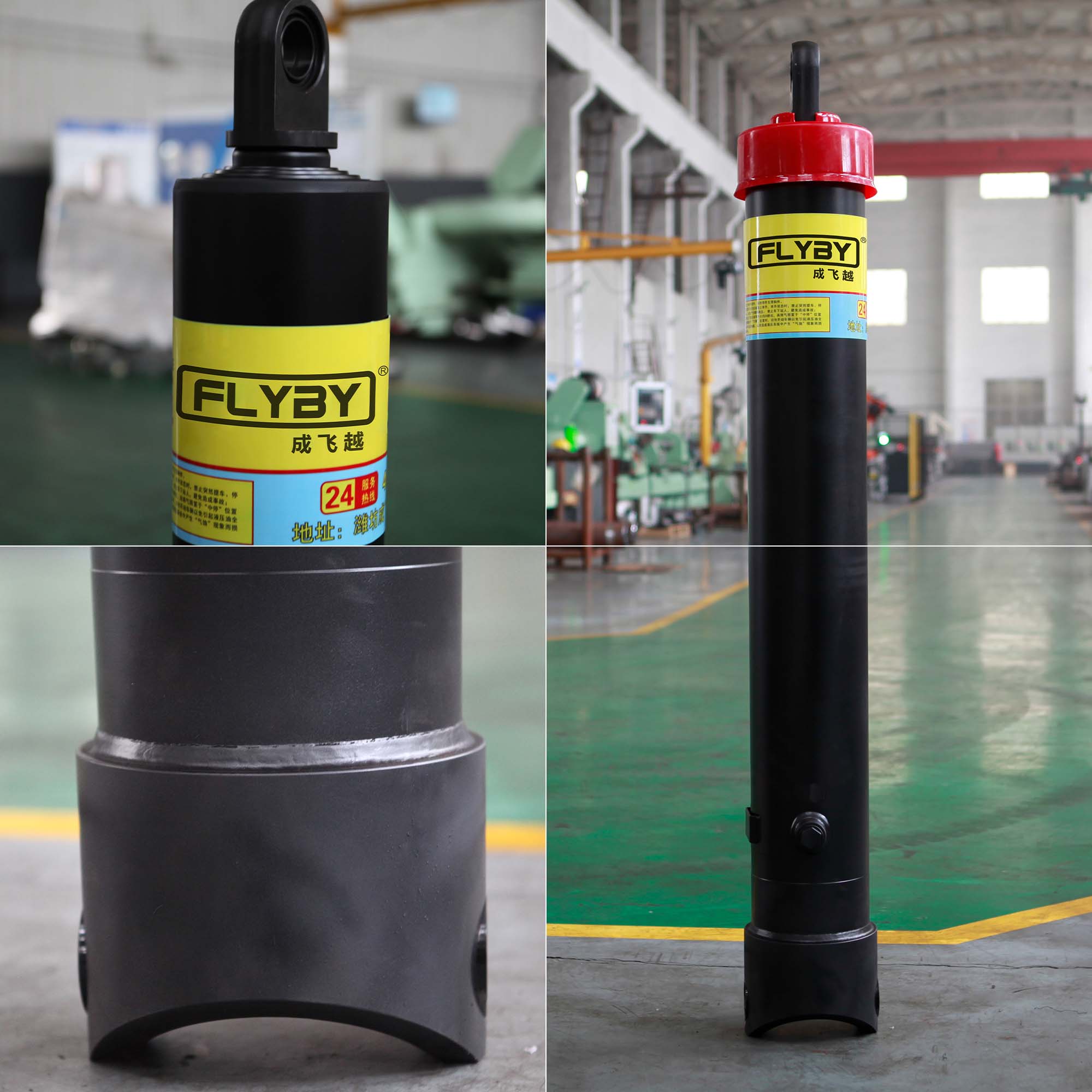
Telescopic configurations dominate the heavy trucking space for good reason. Multi-stage front-end cylinders handle exceptionally long strokes and heavy payloads best. They collapse into a compact footprint while offering massive extension. Single-stage underbody models fit tight chassis spaces and handle lighter capacities efficiently. You must match the cylinder geometry to your specific daily material hauling tasks.
Your procurement team needs exact specifications to succeed. Hand these technical details directly to your chosen manufacturer to avoid costly mismatched components:
Exact pivot mounting distances from the rear hinge.
Maximum system pressure ratings of your current pump.
Required dump angle (typically falling between 45 and 50 degrees).
Extreme environmental operating conditions, including temperature swings.
Successful hoist design requires balancing hard math with operational geometry. You cannot rely on static load calculations alone when facing unpredictable job sites. Always enforce strict safety margins to protect your fleet from catastrophic rod buckling failures. Ensure your system accounts for peak breakaway torque before finalizing any purchase order.
Take these actionable next steps to secure your design:
Verify your breakaway angle geometry physically before running formulas.
Apply a 15% friction deduction to all theoretical pressure estimates.
Mandate a 3:1 safety margin against compressive rod buckling.
Consult a certified fluid power engineer with your exact chassis dimensions.
A: You calculate this by evaluating the initial breakaway angle. Lifting a dump trailer is a rotational torque problem. You must find the pivot distance and calculate the mechanical disadvantage. Then, apply the foundational formula: Force = Pressure × Area. Always size for the heaviest load at the lowest, flattest angle.
A: Yes, it does. There is an inverse relationship between cylinder volume and extension speed. If your pump flow remains constant, a larger bore takes longer to fill. To maintain fast cycle speeds with a larger bore, you must upgrade your pump to deliver higher fluid volume per minute.
A: Standard dump truck systems typically operate between 2,000 to 3,000 PSI. You must calculate pressure based on your specific load and bore size. Exceeding rated pressure limits compromises rod seals and drastically increases burst risk. Always verify your pump and relief valve settings match the cylinder's rated maximum.
A: Multi-stage sizing must account for decreasing surface area. As each progressively smaller stage extends, the force output drops. The final, smallest sleeve dictates the maximum lifting capacity at full extension. You must ensure this final stage can still support the dump bed weight when fully raised.