Views: 0 Author: Site Editor Publish Time: 2026-10-22 Origin: Site
Dump truck design involves a constant, high-stakes engineering conflict. Manufacturers and operators must maximize the payload ejection angle while strictly conforming to highly rigid chassis space constraints. Choosing the wrong cylinder dimensions creates severe downstream consequences. It goes far beyond simply experiencing poor dumping performance on a job site. Incorrect sizing directly leads to bed mounting failures, extremely unstable dumping cycles, or catastrophic side-loading events. You need a highly clear methodology for balancing the retracted footprint against your total extension requirements. This guide explains exactly how to evaluate and spec the correct cylinder for your specific commercial chassis. You will learn how to navigate the critical geometric ratios between the truck's rear hinge point and the primary mounting brackets. We will explore how stroke and retracted dimensions interact, ensuring safe, reliable, and complete material ejection during every single operational cycle.
Closed length strictly dictates frame fitment, trunnion placement, and bed resting height.
Hydraulic cylinder stroke determines the final dump angle; miscalculating leverage points can leave sticky loads stranded in the bed.
Increasing telescopic cylinder stages improves the stroke-to-closed-length ratio but introduces complex maintenance variables like retract mis-staging.
Accurate specification requires factoring in a dead-head safety margin to prevent mechanical bottoming under load.
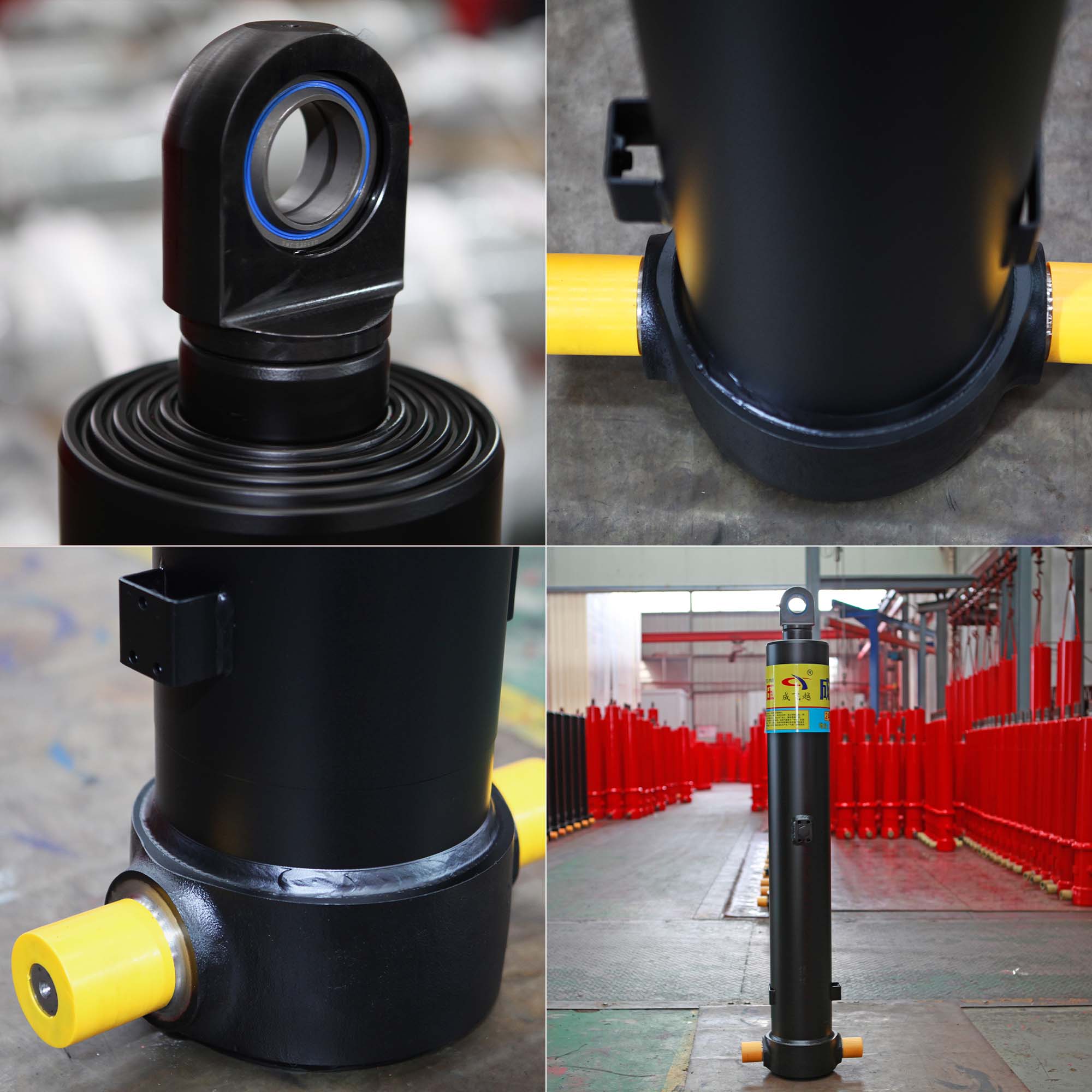
Engineers must establish precise definitions before evaluating various hydraulic options. Pin-to-pin retracted length measures the physical envelope when the unit sits fully collapsed. Total operational stroke represents the maximum linear distance the internal rod and sleeves travel. Standard single-rod cylinders often fail completely in heavy-duty dump applications. They simply cannot achieve high extension ratios from highly confined mounting footprints. This physical limitation makes telescopic designs absolutely mandatory. These specialized units house multiple nested internal sleeves to pack maximum reach into minimum chassis space.
You should not view this engineering decision as merely choosing a convenient size. Instead, view it as calculating a strict geometric ratio. We must perfectly balance the truck's rear hinge point, the forward mounting bracket position, and the required lift arc. A tiny miscalculation here destroys overall lifting efficiency. It places severe, unnecessary mechanical stress on the chassis frame and body rails. You must harmonize the hydraulic cylinder stroke with the available mounting envelope to guarantee reliable, long-term operation. Every fraction of an inch matters when dealing with heavy payloads. Proper geometry ensures maximum lifting power without overstressing the vehicle's structural integrity.
Proper fitment always begins by accurately assessing the retracted dimensions of your equipment. You must measure the resting state envelope correctly to avoid costly installation errors. Always measure from center-of-pin to center-of-pin or center-of-trunnion to center-of-pin. Never measure just the outer barrel body. This critical pin-to-pin measurement strictly dictates the physical resting position of your dump bed.
This dimension heavily influences the required depth of the dump body "doghouse." The doghouse is the specialized recess fabricated into the front of the dump body. A longer retracted unit requires a significantly deeper doghouse to maintain a low, aerodynamic bed profile. Furthermore, this measurement dictates your overall chassis ground clearance. You must ensure the lower trunnion mounts do not hang dangerously low below the truck's frame rails.
Over-speccing the closed length creates severe implementation risks. If the cylinder is physically too long, the dump bed cannot sit flush on the frame. It will rest entirely above the chassis rails. This artificially raises the vehicle's center of gravity. A high center of gravity severely compromises driving stability on highways. It dramatically increases rollover risks during transit and makes high-speed cornering extremely dangerous for the operator.
Material ejection relies entirely on gravity and precise mechanical leverage. Industry-standard success criteria usually target a highly specific dump angle. Operators typically need 45 to 50 degrees of tilt for standard applications. Dry gravel and loose topsoil slide out easily at lower angles. However, sticky materials like wet clay or freezing asphalt demand far steeper angles to clear the bed completely.
You must reverse-engineer the required extension distance to achieve these targets. Start your calculations at the rear hinge-pin placement. Measure the exact linear distance from this rear hinge to the lower cylinder mounting pivot point. Use basic trigonometry to map the required vertical lift arc. This fundamental mathematical framework reveals the exact cylinder stroke length needed to hit your target tilt safely.
Hydraulics experts strongly advise building in an authoritative safety margin. You should subtract roughly 1/2 to 1 inch from your mathematically calculated maximum stroke. This vital margin prevents the cylinder from structurally dead-heading at peak extension. Dead-heading occurs when the internal sleeves slam violently into their physical stop rings under full hydraulic pressure. Incorporating this safety margin protects delicate internal seals, reduces metal fatigue, and actively prevents catastrophic barrel bursting under heavy loads.
You can pack enormous vertical reach into remarkably tight spaces by adding nested internal sleeves. Distributing the total movement across 3, 4, or 5 telescopic cylinder stages allows massive extension from a highly compact base. Each successive sleeve slides out seamlessly from within the larger outer barrel as pressure builds.
This multi-sleeve design introduces specific performance trade-offs.
Chassis Integration: A multi-stage unit fits much tighter mounting constraints. It enables far steeper ejection angles without altering your foundational frame dimensions.
Cost and Maintenance: Higher stage counts mean higher manufacturing costs and more internal seals to maintain. They also experience slightly reduced structural rigidity at peak extension.
System Demands: More stages demand significantly increased fluid volume from your primary hydraulic pump and storage reservoir.
Telescopic Stage Configuration Analysis
Stage Count | Retracted Profile Constraint | Relative Cost Impact | Fluid Volume Requirement |
|---|---|---|---|
3-Stage | Requires moderate mounting space | Lower initial investment | Standard reservoir capacity |
4-Stage | Fits tight chassis designs | Moderate investment | High volume requirement |
5-Stage | Fits ultra-compact footprints | Premium investment | Maximum reservoir capacity |
You must also carefully consider single-acting versus double-acting operational designs. Gravity-drop single-acting systems dominate the dump truck industry. They simply rely on the heavy bed's physical weight to push hydraulic fluid back into the reservoir. Sometimes applications demand powered retraction. This limits your available stage configurations. Double-acting units require complex internal porting systems. This internal complexity adds significant bulk to the retracted envelope compared to standard gravity-drop systems.
Real-world operations consistently expose these complex mechanical systems to extreme physical stress. Retract mis-staging represents a highly common, frustrating operational failure. A 4-stage unit might extend perfectly smoothly but hang up during the gravity retract cycle. Internal pressure traps or severe physical scoring cause individual sections to bind. This sequence disruption leads to sudden, violent bed drops as trapped pressure eventually equalizes.
Maximizing your physical extension also heavily amplifies system vulnerability to lateral forces. When fully extended, the nested sleeves act exactly like a long, fragile lever. If a driver parks the chassis on uneven, sloped ground, the heavy payload shifts sideways. This dangerous side-loading bends chrome rods and completely shatters internal gland rings. Telescopic units are engineered solely for pushing vertically, never for resisting horizontal side forces.
Mounting alignment remains absolutely critical throughout the entire lift arc. You must utilize self-aligning spherical bearings or guarantee precise trunnion leveling during installation. If the upper and lower mounting pins fall out of alignment by just a few degrees, the unit binds. Binding creates massive internal friction, destroying seals prematurely and permanently warping the outer steel barrels.
Selecting the perfect hydraulic unit requires a methodical, systematic approach. We recommend following this strict specification checklist before finalizing any equipment order:
Verify available chassis mounting space precisely to determine your absolute maximum retracted footprint.
Calculate the required hinge-to-pin lift distance based on your target ejection angle and payload type.
Select the appropriate stage count necessary to bridge the gap between space limits and extension needs.
Match the total required fluid displacement exactly to your system pump and hydraulic reservoir capacity.
You must then strategically decide on your primary procurement actions. Standard off-the-shelf configurations work exceptionally well for conventional rectangular dump bodies. They offer significantly lower costs and immediate parts availability. They suit standard gravel trucks perfectly.
However, non-standard dump bodies often require commissioning custom-machined cylinders. If you run heavy-duty rock tubs, specialized municipal plows, or extreme-angle demolition bodies, custom manufacturing ensures safe, proper fitment. Custom specifications prevent dangerous equipment mismatching that frequently compromises overall vehicle safety. Always prioritize structural safety over minor cost savings when finalizing your heavy-duty equipment builds.
Balancing physical footprint against extension capacity remains a strict exercise in precise geometry and physics. It is never a matter of guesswork or rough estimation. You must deeply respect the physical structural limits of your vehicle frame. Ensure your design measurements reflect actual pin-to-pin distances rather than rough barrel lengths. Always factor in a safe operational margin to protect the internal seals from destructive mechanical bottoming.
Gather your precise chassis measurements, maximum payload capacity, and target material ejection angle. Bring these detailed specifications to a highly qualified hydraulics engineer. They will finalize your system design safely and efficiently. Proper alignment and precise geometry guarantee your heavy equipment operates smoothly and reliably on every single job site.
A: You must measure from the exact center of the mounting pin to the center of the opposite pin while the unit sits fully collapsed. Never measure just the overall barrel body length. This precise pin-to-pin measurement accurately represents the true mounting envelope required for proper chassis fitment.
A: No. While the extension dictates the final angle, simply installing a longer unit invites disaster. Exceeding the structural limits of your rear hinge or chassis clearance causes severe mechanical binding. It heavily increases the risk of side-loading and catastrophic vehicle tip-overs during dumping.
A: Mis-staging happens when sequential sleeves hang up or move entirely out of order. This usually stems from payload imbalances, trapped pressure in double-acting units, or physical scoring on specific metal stages. Contaminated hydraulic fluid also clogs internal ports, disrupting the smooth transfer of fluid.