Views: 168 Author: Site Editor Publish Time: 2026-07-17 Origin: Site
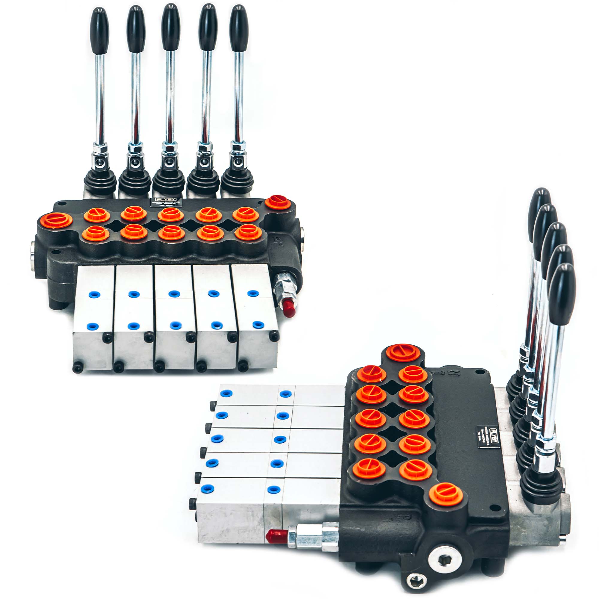
Undersizing a hydraulic valve causes severe fluid overheating and sluggish actuator responses. Conversely, oversizing creates unnecessary bulk and wastes valuable mounting space. You must match your system correctly to ensure optimal performance. The P-Series models—specifically the P40, P80, and P120—serve as the global industry standard for monoblock hydraulic control. You will find them heavily utilized across mobile and industrial equipment worldwide. They offer unparalleled reliability in harsh, high-vibration environments.
This technical guide provides a detailed evaluation framework to help you select exact specifications for your machinery. You will learn how to properly match system flow rates, evaluate port sizing, and determine the optimal number of spool sections. We will explore the critical steps to selecting the right Directional Control Valve so you can avoid dangerous pressure drops and ensure seamless machinery operation.
P40 Series: Ideal for compact, low-flow systems (up to 40 LPM / 11 GPM); supports up to 7 spools; commonly used in small tractors, log splitters, and light agricultural setups.
P80 Series: The mid-range standard (up to 80 LPM / 21 GPM); supports up to 6 spools; balances footprint and capacity for skid steers, medium loaders, and municipal trucks.
P120 Series: Engineered for heavy-duty, high-flow applications (up to 120 LPM / 32 GPM); limited to 1-4 spools; strictly for large excavators, heavy forestry equipment, and industrial rigs.
Sizing Rule: Valve flow rating must always exceed the maximum output of the hydraulic pump to prevent severe pressure drops (ΔP) and system overheating.
Equipment builders and machine retrofitters constantly face a significant mechanical challenge. They need highly reliable, leak-resistant fluid control. However, they rarely have the luxury of excessive mounting space. Traditional tie-rod sectional valves offer customization but introduce numerous potential failure points. Every slice in a sectional valve requires O-rings. When heavy equipment vibrates over rugged terrain, these individual sections can separate slightly. This separation leads to weeping fluid and lost system pressure. Monoblock architecture solves this exact business problem by eliminating the slices entirely.
The P-Series utilizes a cast iron monoblock construction. Manufacturers pour high-grade iron into a single, solid mold to create the entire valve body. This solid-state design delivers exceptionally high pressure tolerance. You eliminate the micro-leaks common in sectional alternatives because there are no seams between the spools. The rigid casting also prevents spool binding under extreme thermal expansion.
Beyond structural integrity, P-Series models share several standardized design advantages:
Integrated Pressure Relief Valves: Every unit includes an adjustable PRV. This built-in safety mechanism protects the pump from deadheading. It also eliminates the need to plumb a separate relief block into your hydraulic circuit.
Default Open Center Configuration: By default, fluid flows freely from the pump straight through the valve and back to the reservoir when all spools rest in neutral. You can easily convert these units to Closed Center operation using a specific threaded plug.
Standardized Spool Types: You can select cylinders optimized for double-acting motion, single-acting gravity returns, hydraulic motor continuous spin, or specialized float functions.
Selecting between the three primary P-Series models requires strict adherence to fluid dynamics. The internal gallery size of the cast iron block dictates how much oil can pass through before generating restrictive friction. We measure this friction as pressure drop (ΔP). When you force too much fluid through narrow galleries, the flow turns turbulent. This turbulence rips energy away from the actuators and converts it into pure heat. High temperatures quickly degrade oil viscosity and destroy hydraulic seals.
Valve Series | Nominal Flow Rate | Maximum Pressure | Standard Port Sizes |
|---|---|---|---|
P40 | 40 LPM (11 GPM) | 31.5 MPa (4500 PSI) | G 1/2" or SAE 8 |
P80 | 80 LPM (21 GPM) | 31.5 MPa (4500 PSI) | G 1/2", G 3/4", or SAE 10/12 |
P120 | 120 LPM (32 GPM) | 31.5 MPa (4500 PSI) | G 1" or SAE 16 |
Evaluating the P40 requires understanding its compact nature. It offers a nominal flow limit of 40 liters per minute. Maximum pressure easily reaches 31.5 MPa depending on the specific casting quality and manufacturer tier. Standard A and B work ports usually utilize G 1/2" or SAE 8 threads. The small internal coring makes it highly responsive but strictly limits its total fluid capacity.
Stepping up to the mid-tier option means evaluating the P80 directional control valve. This model handles double the volume at 80 LPM. The maximum pressure rating remains identical at 31.5 MPa. However, the standard ports scale up significantly. You will typically see G 1/2", G 3/4", or SAE 10/12 porting. Implementing this model requires thicker hydraulic hoses. Your steel fittings must also accommodate the higher flow rate without bottlenecking the fluid path at the connection points.
Heavy machinery necessitates evaluating the P120 directional control valve. This massive unit commands a nominal flow of 120 LPM. The standard ports jump to G 1" or SAE 16. Integrating this valve requires significant physical mounting space on the chassis. You must also use heavy-duty line integration to prevent hose whip under extreme flow conditions.
Your primary decision matrix relies on one simple rule. You must compare the hydraulic pump output directly to the valve's nominal rating. If your pump pushes 15 GPM, you cannot use a P40 rated for 11 GPM. Exceeding nominal flow by even 10% generates disproportionate heat. It wastes engine horsepower because the pump must fight internal valve restriction before moving the cylinder.
Monoblock valves restrict your ability to modify the circuit later. Because the housing consists of one solid casting, you cannot bolt on an extra section if you decide to add a new hydraulic implement next year. You must purchase the exact number of required sections from day one. This physical limitation varies depending on the fluid capacity of the block.
The internal coring required to pass larger fluid volumes dictates the maximum number of spools the foundry can safely cast. Here is how scalability breaks down across the series:
P40: Available in 1 through 7 sections. The small galleries allow the casting to remain stable across a long block.
P80: Available in 1 through 6 sections. The larger fluid channels require thicker internal walls, reducing the maximum possible length.
P120: Available in 1 through 4 sections. The massive internal coring required for high flow makes a 5-spool or 6-spool casting structurally unsound and prone to internal cracking.
Beyond spool count, operators must interact with the valve safely and efficiently. Manufacturers offer multiple control mechanisms to translate human intent into mechanical action. Your choice directly affects operator fatigue and machine precision.
Manual Lever: This remains the standard, most reliable method. Direct physical levers provide excellent tactile feedback. Operators can "feel" the load shifting and feather the cylinder movement accordingly.
Pneumatic/Air Control: You utilize small air lines to shift the hydraulic spools. This proves ideal for dump trucks or applications requiring remote cabin operation. It keeps high-pressure hydraulic lines outside the operator cab.
Cable/Joystick Control: Engineers use heavy-duty push-pull cables connected to a central joystick. This is absolutely crucial for multi-axis simultaneous control. A front-end loader operator relies heavily on this setup to lift the boom and curl the bucket simultaneously.
Electro-Hydraulic (Solenoid): You mount 12V or 24V electrical coils onto the spool ends. This method becomes necessary for automated systems. It allows seamless integration with joysticks, microcontrollers, and complex PLC machinery.
Matching the valve to the machinery goes far beyond just reading the specification sheet. Different equipment categories operate under distinct duty cycles. A log splitter resting in a residential garage experiences entirely different stress loads compared to a mining rig operating continuously underground.
Light equipment falls squarely into P40 territory. You will find these blocks on log splitters, small tractor attachments, mechanical sweepers, and DIY hydraulic shop presses. Tractors utilizing rear remotes or front grapples rely on the P40 extensively. The compact footprint fits perfectly into tight spaces under operator seats or along narrow implement tongues. Most importantly, the 11 GPM maximum limit perfectly covers the standard gear pumps found on small gasoline engines. The system remains light, responsive, and easy to mount.
Medium-duty mobile equipment represents P80 territory. This encompasses skid steer attachments, small knuckle-boom cranes, skip loaders, and agricultural combine harvesters. These machines bridge the gap between utility and industrial performance. A typical mid-sized PTO pump outputs between 15 and 20 GPM. The P80 block handles this fluid volume effortlessly without generating excess backpressure. An operator using a skid steer forestry mulcher needs fast recovery times and robust heat management. The larger internal galleries ensure the fluid remains cool during repetitive, aggressive cycling.
Heavy machinery exclusively commands P120 territory. This category includes mining equipment, heavy forestry processors, large drilling rigs, and industrial scrap balers. These machines utilize massive hydraulic cylinders and high-torque motors. They often feature variable displacement piston pumps capable of pushing immense volumes of oil instantly. The P120 can safely manage this massive fluid displacement in continuous-duty cycles. The robust cast iron walls absorb the immense shock loads generated when a drilling rig bites into solid rock or an excavator boom suddenly stops a heavy swing.
Sourcing and installing hydraulic components introduces several hidden technical risks. Even if you calculate the flow rate perfectly, poor implementation can destroy a hydraulic pump in seconds. You must execute strict procurement checks before finalizing any system design.
Thread standardization risks represent the most common point of failure during installation. Sourcing errors frequently occur between BSPP (British Standard Pipe Parallel) and SAE or NPT standards. European manufacturers heavily favor BSPP. North American systems rely almost exclusively on SAE O-Ring Boss or NPT threads. If you force an NPT fitting into a BSPP cast iron port, you will permanently cross-thread the housing. It will leak instantly under pressure. Always ensure the valve housing matches your existing hydraulic lines. You want to avoid using weak adapter stacks. Every adapter you add creates a new potential leak point and restricts fluid flow further.
Open versus Closed Center compatibility requires your immediate attention. Installing a standard open-center monoblock in a closed-center load-sensing (CCLS) system causes catastrophic failure. A closed-center pump constantly maintains maximum system pressure. If you route that pressure into an open-center valve, the fluid simply dumps back to the tank. The system loses all pressure. Conversely, if you put a closed-center valve on a fixed-displacement open-center gear pump, the pump has nowhere to push the fluid when the spools rest in neutral. The pump deadheads, the internal casing cracks, and the equipment shuts down. Always verify if a closed-center conversion plug comes included in the box.
Finally, never trust factory relief valve pre-sets implicitly. Most manufacturers ship monoblock valves with the main relief pre-set around 175 bar (2500 PSI). Your specific system might only tolerate 2000 PSI before blowing cylinder seals. Alternatively, your machine might require 3000 PSI to lift its rated load. Outline a strict commissioning procedure. You must install an inline pressure gauge on the inlet port before starting the engine. Warm up the hydraulic oil. Deadhead a cylinder to force fluid over the relief. Then, adjust the PRV safely to meet your system-specific requirements.
Selecting between the P40, P80, and P120 series requires a precise understanding of your machine's mechanical limits. The final summary judgment is straightforward. Your choice is strictly dictated by the hydraulic pump's maximum flow rate and the physical space available for mounting the cast iron block. Do not attempt to force high volumes of oil through undersized internal galleries.
As you move forward, execute three critical action steps. First, check your hydraulic pump's GPM or LPM specification plate to establish your baseline flow requirement. Second, count the exact number of actuator circuits your machine needs to operate simultaneously, keeping the block's maximum spool limits in mind. Third, verify your existing port thread types to ensure seamless integration. Following these steps guarantees optimal equipment performance and eliminates unnecessary mechanical stress.
A: Yes. Oversizing a valve is perfectly safe. The larger internal galleries easily accommodate the lower fluid volume. This approach significantly reduces pressure drop and keeps the hydraulic oil cooler. However, oversizing increases the physical footprint of the valve block and adds unnecessary component weight to your machinery.
A: Pushing high flow through restricted ports creates a severe pressure drop (ΔP). The fluid dynamics turn highly turbulent. This restriction generates massive heat, quickly breaking down the oil's viscosity. You will experience extremely sluggish cylinder speeds and risk blowing the internal hydraulic seals due to excessive backpressure.
A: Yes. Most P40, P80, and P120 models accept a specialized Power Beyond sleeve. You remove a standard plug and insert the sleeve. This allows high-pressure fluid to be safely routed downstream to another control valve rather than dumping all the returning fluid directly into the low-pressure tank.
A: No. Because the manufacturer casts the entire housing as a single solid iron block (monoblock), you cannot add or remove sections later. You must accurately calculate and specify the exact number of spools required for your hydraulic circuit at the time of purchase.